The Best Way To Align Your AM Receiver
By Bill Jones
This note will cover only the tube type Superheterodyne receiver, and the ways that it can be aligned. The main theme of the article will be the alignment of the Intermediate Frequency (I.F.) transformers. However, the Radio Frequency (R.F.) stages will be considered. The alignment may depend on how you use the receiver, and this will be discussed.
It is a surprise to most radio collectors that the best way to align your receiver is most often - by not following the manual. The manual is a good way to align the receiver – but not the best way.
The basic alignment requires that you have a s2ignal generator and an AC voltmeter. You will align the I.F. before you align the R.F. stages.
In this process you set the signal generator to the I.F. frequency and connect the signal generator to the converter (also called the “mixer”) grid. The generator is connected through a capacitor to the grid. Connecting the output of the generator through a capacitor keeps the grid voltage from being disturbed. A .01 mfd. capacitor is often suggested, but the capacitor is not critical. I do like to use a large paper capacitor -.005 to .05 mfd. The voltage across the capacitor is around zero. The capacitor keeps the R.F. stage effectively shorted out by the signal generator, and allows any grid bias of the R.F stage to be undisturbed.
A good signal generator will have a low resistance output of fifty ohms to seventy five ohms. Some generators will have a higher resistance output but it will still be low enough to keep the RF stage from interfering with the I.F. alignment. The problem with most signal generators is not the output resistance; it is usually the generator frequency that causes alignment errors. The dial of the generator will be set to the desired frequency, but the output frequency of the generator is seldom correct. There is usually an error in the frequency output. It may be up to 10 percent (plus or minus) what the generator indicates. Having such errors in the generator can be serious if you want your radio have the proper selectivity, and correct dial reading. Such an error will make the I.F. bandwidth either too wide or too narrow.
Assume the I.F. is 455 kiloHertz, and the signal generator has a frequency error of 10 percent (plus or minus). Such an error would put the output frequency of the generator at either 500.5 kiloHertz or 409.5. The I.F. transformers were designed to operate at a certain frequency – 455 kilo-Hertz, in this example. The transfer function of the transformer is mathematically complicated. The transformer is designed to have a flat top as in Figure 1.

FIGURE 1.
The receiver is designed to have a bandwidth of approximately 10 kilo-hertz. Since there are two sidebands the AM transmitted signal will have a bandwidth of about 10 kilo-Hertz. The stations are separated by 10 kilo-Hertz. If you do not set the I.F. correctly the I.F. will have an improper transfer function. Actually if the I.F. transformer frequency is off by as much as ten percent the output frequency versus the signal output could look much like that of Figure 2 or Figure 3.
Few people complain if the radio dial has a slight error, because the exact frequency is often unimportant. There are those that do object to such errors. I want to have a calibrated generator. I want my receiver to also have a reasonably correct dial reading, and the proper bandwidth.

FIGURE 2

FIGURE 3
As shown in Figure 2 it will have too wide a bandwidth with a low output in the middle or the bandwidth will be too narrow as shown in Figure 3. The parameters of the Transmitter and the Receiver bandwidths are set such that the actual adjacent channel interference is down about 40 dB at the high frequency end of the passband.
Few people complain if the radio dial has a slight error, because the exact frequency is usually unknown. There are those that do object to such errors. I want to have a calibrated generator. I want my receiver to have a correct dial reading and the proper bandwidth. There are, however those inexpensive receivers that cannot be set perfectly because of design errors caused by either manufacturing or engineering.
To have a correct reading on your generator usually means your generator will have a crystal calibrator built in the generator. There are only a few of the radio service generators that have crystals built in. The one that comes to mind is the Hickok 288X, and there are different models of the Hickok that have the built in calibrator. The Hickok crystal calibrator is usually off several kilohertz, but this is reasonable. A good solution is to have a frequency counter. If the generator has enough output to run your counter you can then connect the generator to the counter to get the correct frequency. You can also often find a tube laboratory generator at a reasonable price. The Hewlett Packard 606A is a fine laboratory generator, with an excellent crystal calibrator. See my article on the comparison of the Hickok 288X and the HP 606A.
Before beginning alignment there are several things to watch for. These are important because two things that can cause injury to you or to your test equipment. Some older AC/DC receivers have one side of the AC line connected to the chassis. Then depending on how the plug is inserted into the wall receptacle the chassis could be at 120 Volts AC. This is serious and requires that you make some arrangement to always plug the radio into the wall such that there is no AC on the chassis. It is best to have an isolation transformer. Putting a dot of paint on the ground side plug is one possible solution. The other problem to watch out for is that some older radios have B+ on the I.F. trimmer adjusting screws. The later radios got rid of this feature but you should be aware of the possibility. Of course you need to realize that some later radios will have permeability tuned I.F. transformers and they require proper plastic tuning tools to adjust the permeability slugs. It is possible that the slugs will not turn even using the proper tools. It is not unusual to have the slugs stuck because of wax that was often used in the manufacturing of the transformers. A heat gun may free up a stuck trimmer. The permeability slugs are brittle and easily damaged. These permeability tuned transformers will have one adjustment from the top of the I.F. can and one adjustment from the bottom of the can. The adjusting tools for the permeability slugs do not seem to be standard and these tools come in a number of sizes.
Setting the signal generator to the desired I.F. frequency, and then connecting an AC meter to the output of the speaker leads is the next step. The generator modulation is turned on and if four hundred cycles is available I will use that frequency because I find 1000 cycles to be annoying. The radio is turned on and the volume controlled set to the maximum volume. The generator is then turned up to where you can read a voltage on the meter. The purpose of keeping the output of the generator very low is because this allows the receiver to be aligned for small signals.
With the signal generator set at a very low level the Automatic Gain Control (AGC) voltage should be near zero volts. This then keeps the gain of each tube that receives the AGC voltage at a high gain state. When a large signal is received the AGC voltage increases (negatively) and reduces the gain of the receiver tubes that use the AGC. When the gain is reduced the alignment of the Intermediate Frequency (I.F.) is changed because of the so-called Miller effect The Miller effect causes the grid capacitance to change when the I.F. gain is changed. This causes the alignment to change, because the grid capacitance is across the I.F. transformer inductor. The Miller effect is caused by the tube’s plate to grid capacitance. This capacitance is very small for most pentodes, but it does cause a slight capacitance decrease as the negative AGC voltage increases. This then will change the alignment slightly. This is not a serious problem because when the received signal is large a small change in the alignment will not be noticed by a listener. A good small signal alignment will set the receiver bandwidth to a value that is reasonable or put another way it will set the bandwidth close to the design value. This allows the receiver to provide a good signal to noise ratio. Thus, for small signals the best alignment is obtained when the AGC is at a low negative voltage. The generator is then set to a low output for best small signal reception.
There are very few people that use the radio for small signals today. One exception is the Ham radio operators that may receive signals of a few microvolts. In the early days of radio the alignment procedure described was the normal alignment procedure. The reception of a desired station could be difficult if the station was a far distance from the receiver. It was therefore proper to align the receiver for small signals.
Today, most users listen to local stations and in such case it may be best to align the set using large signals. Small signals would be in the order of microvolts and large signals would be in the order of millivolts. The older sets used tubes that had large plate to grid capacitance, but miniature tubes reduced the capacitance significantly.
The way the set is aligned will then depend on how the set is to be used. I normally use a large signal from the signal generator because I listen to local stations. It is a fine point for discussion. Opinions will differ.
I have no reason to suggest which transformer should be aligned first. Radio service manuals usually start with the second I.F, but I see no reason for this except that you have to start somewhere. I like to adjust one transformer, then the second transformer, and then repeat the process to get the largest AC output possible.
The AC voltage indication method of I.F. adjustment is a proper means of adjustment. It requires a minimum of equipment and provides an acceptable alignment of the receiver I.F. for small signals.
An alternate means of alignment for large signals will be described. It does not require a modulated generator. The means suggested provides a good alignment for large signals. This is the way that most radios are used rather than align for small signals.
As in the first method you connect the generator (modulated or unmodulated) to the grid of the mixer tube. Then measure the AGC voltage with a Vacuum Tube Voltmeter. Set the generator frequency output level such that the AGC reads several volts, I would suggest around three or four volts. Vary the generator output to be sure that the AGC voltage follows the generator output. This insures that nothing is limiting in the I.F. amplifier. Now adjust the I.F. transformers for a maximum negative AGC voltage. Turn the generator output down as the AGC voltage increases. Again I would adjust both transformers and repeat the process for a maximum negative voltage. This method of adjustment of the I.F. could of course be used with small signal alignment as well as large signal alignment. The method has the disadvantage of requiring a Vacuum Tube Voltmeter. A good Vacuum Tube Voltmeter will have an input resistance of over ten megohms.
The proper IF curve is shown in Figure 1, and this curve is normally unobtainable in the adjustment means discussed. To not have a flat top on the I.F. curve is not a problem when voice is used, but it can be a problem if transmission of data is desired. Alignment with a flat top as a goal normally means that you have the I.F. transformer set as it was designed, that is, the transformer has the correct bandwidth at the desired frequency.
Having completed either of the above methods does not mean that the I.F. is “correctly” adjusted. The proper I.F. adjustment means that the I.F. curve has a frequency versus output curve that has a flat top as shown in Figure 1. The actual curve that is obtained when using the adjustment methods that have been discussed will generally provide a curve that might look like that shown in Figure 4.
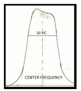
FIGURE 4
The proper I.F. curve is shown in Figure 1. And this curve is normally unobtainable in the adjustment means discussed. A flat top on the I.F. curve is not normally a problem if transmission of data is not desired. Alignment with a flat top as a goal normally means that you have the I.F. transformer set as it was designed, that is, the transformer has the correct bandwidth at the desired operating frequency.
The curve should look like Figure 1 and the I.F. transformer design is mathematically designed to be flat with the correct bandwidth. This is very unlikely to be obtained by the means we have discussed. It is likely to look like Figure 4 with a good probability that it will look much worse than Figure 4.
To make to the alignment curve have a flat top as in Figure 1 it is necessary to have a sweep generator, and oscilloscope available. This equipment is expensive and is slightly difficult to use without experience.
When you can see the actual I.F. curve on the oscilloscope you can get a flat top by adjustment of the I.F. transformers. I like to see a proper curve, but it is of some bother to set up the sweep generator and oscilloscope. I would not go to this trouble unless I had an expensive radio or communication receiver to align. The communications receiver will normally have a gain greater than the home receiver. The good communication receivers will have an optimum signal to noise ratio when the alignment is correct. This is important for receiving small signals.
The radio frequency amplifier is easier to adjust. Getting the signal into the receiver can be a problem. If your generator has an output adjustment in the order of microvolts then you only have to connect the generator directly to the antenna input. If your generator only puts out millivolts then you may have to couple using a large resistor or small capacitor to couple to the receiver.
Using a laboratory generator such as the HP 606 will allow you to get any output you would like –from a microvolt to over a Volt.
If your receiver has a loop antenna then a short wire from the generator will often work by putting the wire close to the receiver loop or you can make a loop of several turns of wire for the signal generator output. Set the generator loop close to the receiver loop and you should receive a signal from the generator.
Set the receiver frequency to its high end of the dial. For example the high end might be 1600 kiloHertz. I would use a Vacuum Tube Voltmeter for a tuning indicator, but the AC meter on the audio output is good as long as the generator is modulated.
With the generator set to 1600 kilohertz, adjust the receiver tuning dial for a maximum indication. The dial should read 1600 kiloHertz. But if it does not the oscillator trimmer must be adjusted to make the dial read 1600 kiloHertz. Now adjust the R.F. trimmers or trimmer for a maximum reading on your indicator.
Set the generator to the low end of the receiver dial, usually about 600 kiloHertz and adjust the receiver for a maximum reading. The dial should of course read the same as the generator. To adjust the low end of the dial will depend on the type of receiver that you have. If your receiver oscillator variable condenser has the same type of plates as the R.F. variable condenser then the oscillator variable condenser has a trimmer capacitor in series with the oscillator variable condenser. This trimmer is called a padder capacitor and the padder is adjusted for the low frequency dial accuracy. This low frequency adjustment is usually done by setting the generator to around 600 kiloHertz or whatever the manual shows. The padder is then adjusted to receive the signal from the generator. In practice, you actually tune the receiver until the 600 kiloHertz from the generator is received and then the padder is slightly adjusted to move the dial to the correct position. You then go back to the high end of the dial and readjust the high end if necessary. The low end is then rechecked.
If your receiver oscillator has “cut plates” – that is the oscillator rotor plates are cut smaller than the R.F. plates then if the dial does not read correctly, and you are not satisfied with the reading you have to bend the oscillator plates either in or out to correct the reading. Some variable capacitors have slots cut in the outside plates to allow bending. If you bend the plates then it is necessary to recheck the high end R.F. trimmer. While many variable capacitors have the slots available for bending there are few technicians that have the knowledge of how to bend the plates properly. It is unusual to find a radio with the plates bent. The manufacturers do not bother to check this alignment because it is time consuming.
There are a number of web articles on the alignment of these receivers. You should review a few of the articles if you have not done an alignment before. There are receivers that have not been covered here and it would be good to acquaint yourself with the alignment procedure from other viewpoints.
You may want to adjust your RF amplifier for small signal or for large signals. Again this is a fine point especially for the RF amplifier because the bandwidth for these amplifiers is normally quite large, and the actual receiver bandwidth is determined by the I.F. amplifier. You may have two RF amplifiers with a three gang variable condenser which means that you have two RF amplifiers to adjust. A few radios have two RF amplifiers but only one RF trimmer to adjust. This means that one of the RF amplifiers is broad band with no adjustment necessary.
If you do have more than one tuned RF stage, it is possible that they do not track. That is to say that one may be set to have the maximum output for one frequency while the other has a maximum output for a different frequency. This is normally difficult to detect without a sweep generator and oscilloscope.
Alignment is an interesting process. We have covered the simple AM receiver. There are receivers that are not so simple. For example there are many F.M. tube receivers, and these receivers are somewhat complex. I would refer you to the manual for this type of receiver since there are several types of F.M. discriminators that are used, and the discriminator alignment depends on the particular set. I work on F.M. receivers, but when I work on these sets I will normally use the manual for alignment.


Comments
Post a Comment